9 - Shortest Path Algorithms

Recall from the lab that:

Some general routing issues to consider:

  • We may need to forward out on the correct interface towards the destination
  • Use (create): The Routing Table

Here in this possible path between two devices (in red), we may want to optimize:

  • Hop count (smaller is better)
  • Shortest distance
  • Speed (some cables may be higher speeds)
  • Bandwidth
  • ...
    For all of these, we generate a cost using these factors. For each router, we'll calculate the shortest path (in terms of cost) to each destination. Each router will have their own Routing Table and calculate their own cost.

A routing decision is made on every single packet, so each IP Addressing (IP Protocol) datagram is processed, and we search for an existing destination IP in the Routing Table. Where is this done? On every router.

The routing goal is to find the least cost route from the source to the destination. In effect, it creates a logical shortest path tree Network Topologies over the physical topology (ie: it's a minimum cost spanning tree). We'll look at Dijkstra's and Bellman-Ford.

Process to Develop the Routing Table

We'll make an Adjacency Matrix that describes the number of edges between two points on the graph. For now, assume we only care about hop count (so no weights on the edges yet):

Then for this example network we have:
[0110010110110100110100010]
Then you can run Dijkstra's algorithm, taking powers of this adjacency matrix to get the cost of taking a path from any vertex to another.

If you wanted to add in the weights you could:
[0510050320130100210200020]
You can also add make the graph directed. You just consider the in-degree using those weights (using the in-vertex on the rows, out-vertex on the columns; really the order doesn't matter as you'll get the transpose if you do it the other way).

Distance Vector Routing

The distance vector routing protocol only considers hop count, and nothing else. It generates a next hop count table:

  1. Collect the Hop Count Data
  2. Process
  3. Generate Hop Count Table AND the Routing Table.

Consider the example from before again. The routers that are neighbors will only share their hop count table with each other. So A will only share with B,C, and vice versa.

Hop count table for A:

Dest. Subnet Hop Count Next Hop
B 1 B
C 1 C
Note that these are shared initially (with the neighbors). For B:
Dest. Subnet Hop Count Next Hop
A 1 A
C 1 C
D 1 D
For C:
Dest. Subnet Hop Count Next Hop
B 1 B
A 1 A
D 1 D

Next is the traffic for these requests get forwarded, so for the example below A shares the B traffic to it's neighbor C:

GIving the following tables:

A:

Dest. Subnet Hop Count Next Hop
B 1 B
C 1 C
D 2 C
B:
Dest. Subnet Hop Count Next Hop
A 1 A
C 1 C
D 1 D
E 2 D
C:
Dest. Subnet Hop Count Next Hop
B 1 B
A 1 A
D 1 D
E 2 D
D:
Dest. Subnet Hop Count Next Hop
B 1 B
C 1 C
E 1 E
A 2 B
We continue. At the end we need to update the 3 hop in A:
Dest. Subnet Hop Count Next Hop
B 1 B
C 1 C
D 2 C
E 3 B
##### Info on the Distance Vector Routing Algorithm

Note that:

  • Each neighbor shares their entire hop count table with each other, and only with each other.
  • One negative is that A only has a local view of the graph. If there are loops (ex: due to a wire that's gone down) then you'll get invalid hop counts (A counts to B and vice versa for forever). This is known as the count to infinity problem

To fix this we have different methods:

  • Set ∞ (the max count) to 16 (so we only look at the nearest 16 hops)
  • You can also just have A (in the example above) if it it sees a count that refers to itself via the next hop, to ignore that (ie: it should only allow outgoing hops, not inward hops).

Distant Vector Routing (ex: RIP)

So this uses "Bellman-Ford's" shortest path algorithm, where each router will only have a local view of the network. We have two sample implementations:

  • RIP - Router Information Protocol
  • RIP2

Some issues include:

  • Scalability (you can only see so many next hops, and you get exponentially more traffic doing this as that count increases)
  • Count to Infinity problem (loops)

Consider the example above. Using the Shortest Path Algorithm (Networking), RIP you can make an adjacency matrix to represent the directed graph.

Who uses this protocol? All other routers on the network.
What does it do: State of its local links
It creates the Link State Datatable (oh boy we love our tables) using Dijkstra's Algorithm, which is this weighted adjacency matrix.

Here's the paths sent to/from the routers after 2 iterations (unweighted path fo 2):

A B C D E
(A,B,2) (B,A,1) (C,A, 4) (A,B,2) (E,D,3)
(A,C,2) (B,C, 3) (C,B,4) (D,E,3)
(B,D,3) (C,D, 4) (D,C,1)

notation: (source router, dest. router, length (in weight))

Adjacency Matrix:

Source (below) Dest (Right) A B C D E
A 2 2
B 1 3 3
C 4 4 4
D 2 1 3
E 3
Essentially A runs dijkstra's algorithm on it's own, and generates the table using links from its neighbors.

Here:

See also Shortest Path Algorithm (Networking), RIP.

RIPv2
• Interior gateway protocol (so within an Autonomous System )
• Distant Vector routing protocol
• Supports subnetting and CIDR addressing
• Including Variable Length subnet masking (VLSM)
• Cost Metric
• Hop count only
• 15 is maximum hop count (so 16 = infinity)
• Updates
• Sent every 30 seconds
• Also triggered by changes

Open Shortest Path First (RFC 2328)
• Interior gateway protocol (so withinAutonomous Systems (AS, Networking))
• Shortest path calculation:
• Link State Routing
• Dijkstra’s Shortest Path Algorithm (Networking), RIP to calculate routing table
• Features:
• Multiple distance metrics
• Dynamic
• QoS
• Load Balancing
• Hierarchical (supports Areas – next slide)
• CIDR support

OSPF Hierarchical routing
• Supports an abstraction called Areas
• Allows for a AS to be further subdivided into areas
• Routers within an Area exchange routing information
with each other
• Routers external to Area only share routing
information with Area edge routers
• Allows for hierarchical routing within an AS

See IGP, EGP (Routing Protocols). This will talk more in-depth info on Exterior Gateway Routing Protocols between primarily Autonomous Systems (AS, Networking).

Here BGP: Border Gateway Protocol is used to route between Autonomous Systems (AS, Networking). They are used to route between ASes. Used to route between Ases :
• Exchanges network reachability information. Says you can get to network X via this path of ASes
• Needs to be concerned with policies (business and political)
• See RFC 1771, BGP-4
• Runs over a reliable transport protocol (TCP)
• Uses a modified Distance Vector Protocol, but really it's Path-Vector Routing

Pasted image 20250206161204.png

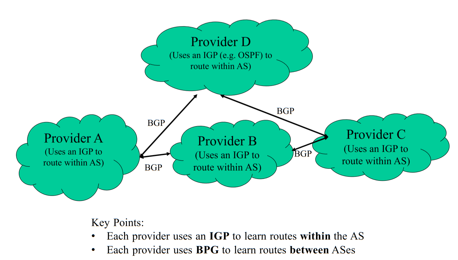
It's important to note that it only exchanges routing information at the AS level. So there is not routing info about the internals of the ASes. It exchanges the full AS path info the the destination IP.

Example

IP 5.0.0.0/8 has path <AS4, AS 9, AS 7, AS 3> from your local machine.

An Example

Here essentially the BGP speakers share with their neighbors, similar to the Shortest Path Algorithm (Networking), RIP, the paths of ASes for each subnet. For choosing a path:

  • If there is no policy, then just choose the shortest path
  • Business Reasons (ex: one may only want to use AS 50 above as a backup to preserve expensive traffic for more $$).
  • All of this is decided within the BGP speaker.
Note

You're Routing Table will not have info on ASes, but on the BGP speaker it routes certain IPs (ex: Cal Polys) to whatever direction its policy says to do.

Interior Boarder Gateway Protocol

How does the information on the BGP speaker get to information within the cloud/AS? Here comes interior Boarder Gateway Protocol (iBGP):

  • Is a modified use of BGP but for interior route distrbution
  • Used in large ASes
    • Redistributes the BGP routes to internal routers
  • Allows internal routers to learn the best gateway (from routes learned by BGP)
  • If iBGP is not used, some other interior route distribution software is needed (so you essentially always need iBGP).