Lecture 9 - Lighting!
No, not lightning, lighting!
Lab 6 is based on making and changing lighting. This will be due this Thursday.
This is the part of the quarter where things are getting easier. Furthermore, Program 3 will take the scenes from Program 2 and add lighting and shading (from lab 6).
Also on the 20th (February) we'll have a guest speaker. Try to come with good questions like:
- What was the best (or worst) bug you've ever experienced?
- What was the coolest thing you worked on?
- ...
In terms of graphics classes being offered in the spring:
- Usually Animation and Real-Time Computer Graphics are offered in spring, but there's missing professors.
- Instead there'll be a CSC 400 course where you just follow independent learning via Wood's related CSC 476 and so on canvas pages.
Lighting and Shading
Recall from last week we wanted to make something like:

For this we need:
- Light Source
- Materials (way to specify reflection)
So we'll need to add some data to define these parameters.
This looks like a 2D scene:

And this more of a 3D scene:

Notice that:
- The light isn't coming from the camera. Hence, our light needs geometric properties.
- Different sides of the surface are shaded lighter or darker.
Thus we need the local shading model. For each pixel, we want to determine if the surface is facing away or towards the light.
We'll also need to have sense of the material itself. Intuitively, we think about this as the color of the object. But it's actually more than that. We also need the type of material:
- A more glassy object should reflect more light
- A piece of plastic or some stone should still reflect light, but definitely less of it.
Different materials in the world reflect light differently in different amounts. This is the Bui-Phong Shading Model, which you'll implement in your Lab 6. Jim Blinn helped this model work better on GPUs, which we'll use in our model (so this is really the Blinn-Shading Model).
What to Add?
You will need data to add to your code for light: either ...
- A point light (only contains position via
vec3), usually modeling a lightbulb. - Directional light (only a direction via
vec3), usually modeling a far-away source, ie: the sun. This helps model a constant vector field (at all points) of some light source. - Spot-light: Has data on both direction and position, both
vec3: The light itself may fall off proportional to distance ie:or via the inverse square via .
We'll have to still consider the CPU and GPU relationship, where now we'll use the fragment shader.
One of Phong's observations is that we can break down the reflected light as:
so the total reflected light is a combination of diffusely reflected light, specular light, and ambient light. This what makes it a local shading model versus a global illumination algorithm, where that is more of a ray tracing-type approach looking at reflections of lights and how they affect other object's light.
Materials
We're going to simplify objects to have different materials. If we zoom in on a smooth surface, we get perfect angle reflectance (giving the shiny look we're familiar with).
But for a rough surface, we get diffuse light, where some of the light gets reflected back:
We define vec3 value like
- How much red is diffused off of the object?
- How much green is diffused off?
- How much blue is diffused off?
Thus, we get the total relationship as:
Recall the dot product:
so then if we normalize the vector (make the magnitude of the vector as 1):
Gives us the total equation:
notice that this dot product gives you a scalar, but multiply with
Some things is that:
- There's no negative light, so use
maxand0as the other parameter so that we either reflect our light positively, or not at all. - Make sure that you normalize your vectors either before or after your calculation.
Ambient light is the light we get from non-light materials. For instance, the bottom of a desk still gets some light since light reflects off of the walls, off the ground, and towards the desk bottom.
Where are the
In the obj file, we have vertex normals:
v 0.7 1.0, 12.0  // vertex v1
...

vn 0.1, 0.2, 0.5 // vertex normal vn1
...

f 1/2/2 ...      // face 1 have the first vertex, with vector normal vn2,
In the obj we'll look at texture coordinate vt 100 0 24 that specify important texture coordinate for the purpose of texturing.
If you're ever just given the vertices, you can just get the normal by getting the cross product of the vectors connected by connecting our vertex in question by the other two vertices in the triangle:
and then once you get the normals, you can use Barycentric Coordinates to interpolate the vertices between the triangle.
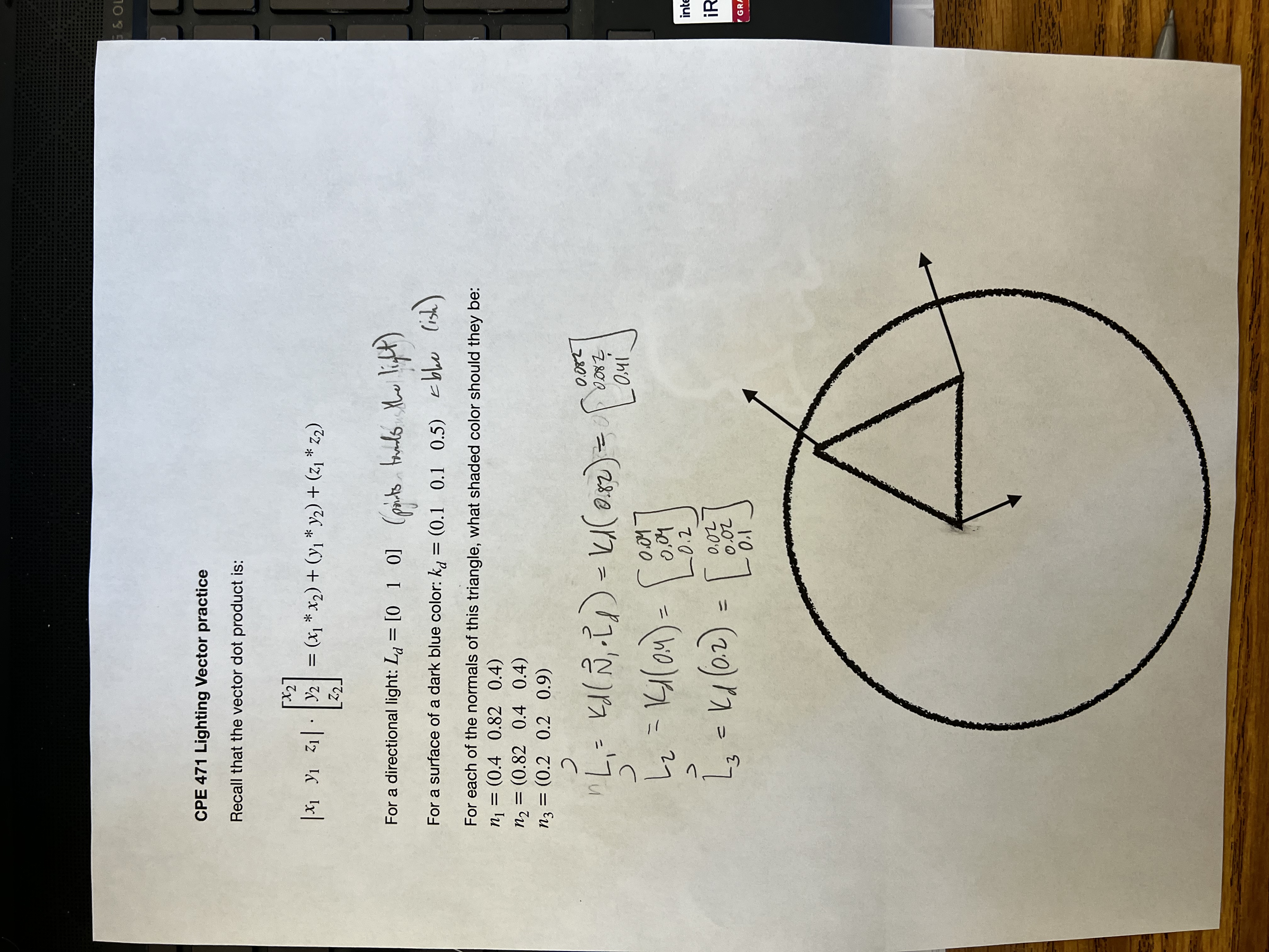
We did the worksheet below that shows this entire process:
- If you have positional light, you'll need to find
between each vertex individually. - If you have a normal vector from an
obj, you'll need to first callV * M * (vecN)